VENTARIS TE

The combination of
Tensor and Ventaris

Ventaris TE

The combination of Tensor and Ventaris

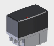
Tensor actuator head
  • Fully electronically controlled precision actuator
  • BLDC brushless DC motor
  • Position- or force-dependent switch-off
  • Wear-free, non-contact position detection via Hall sensors
  • Multiple voltage power supply unit 85 … 265 VAC or 24 VDC
  • Electronic end position setting
  • Programmable additional auxiliary switches (bi-stable relay)

Actuating force

1000...6000

N

Actuating time

0.1...0.8

mm/s

Technical data Tensor
Protection typeIP 65 (optionally up to IP 67)
Ambient temperature–15° C…+60° C (optionally –25° C…+80° C)
HousingPowder-coated die-cast aluminium
Gear unitMetal
CoverPolycarbonate (alternatively aluminium)
Hand wheelExternal (optional)
Position indicatorElectronic
Supply voltage85 – 265 VAC (alternatively 24 VDC)
Additional switches2 or 4 bi-stable relays (optional)
PotentiometerElectronic (optional)
Duty cycle100 %
Connection3 cable entries M16x1.5
Switch offElectronic (wear-free) position- or force-dependent
MaintenanceMaintenance-free permanent lubrication
Actuation3-point step (optional positioner 12 bit, bus, …)
Typ Ventaris TE
Stellkraft (N)100010001000100020002000200020003000300030005000500060006000
Stellzeit (mm/s)0,10,30,50,80,10,30,50,80,10,20,30,10,20,10,2

Other actuating times on request
Ventaris TE – Options

Metal cover

  • Robust and impact-resistant industrial design, aluminium
  • Powder coated

Hand wheel

  • Automatic disconnect
  • Not co-rotating

Position indicator

  • Visualisation of the 7-segment display

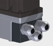
Cable entry adapter

  • For cable gland 3xM20 (instead of 3xM16)
  • Cable entry from front
  • Anodised aluminium

Current output

  • Add-on board
  • Integrated in internal system bus
  • Position feedback 4 – 20 mA
  • Alarm output for signalling readiness
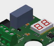
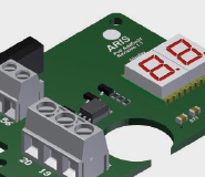
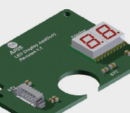
  • With two-digit 7-segment display for easier programming and position display

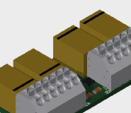
Auxiliary path switches

  • Additional auxiliary path switches with freely selectable switching points
  • Convenient adjustment via on-board keypad
  • Bi-stable design (switching position is retained even when operated without voltage)
  • Version with 2 or 4 additional switches

PCB I-ACT

(Add-on)

  • Electronic potentiometer
  • Controller card
  • Position indicator
  • Current output
  • Special functions

Potentiometer PCB

  • Add-on board
  • Integrated in internal system bus
  • Electronic potentiometer
  • Impedance 1 kOhm
  • Automatic adjustment to the configured control path of the actuator
  • 100 % utilisation of the potentiometer range
  • Manual adjustment via on-board keypad if necessary
  • Can be used as a voltage divider
  • Alarm output for signalling readiness
  • Two-digit 7-segment display for easier programming and position display

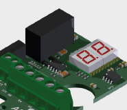
PCB plain text display

(7-segment)

  • Double 7-segment display
  • Position displayed in percentage
  • Rotary direction indicator
  • Menu navigation in programming process
  • Standard with optional potentiometer, I-ACT and current output