

Overview of the gas control system
All components required for gas treatment and regulation with the legally required approvals
(European standard, in some cases DVGW)

01.
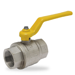
Shut-off ball valve
For isolating the gas control line from the supply.
02.
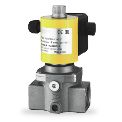
Solenoid shut-off valve
For gas separation, e.g. triggered by a gas detector.
03.
Manually operated quick-closing valve
For quick and safe closing with minimized pressure loss when open.
Remote monitoring is possible; the closing process is faster and safer than with conventional ball valves.
04.
Pressure gauge
The pressure gauges are installed to monitor the upstream and downstream pressure.
A shut-off valve is connected upstream of each pressure gauge to allow easy replacement of the pressure gauges in the event of a fault.
05.
Gas filter
protects the rest of the system from dirt or dust that is carried along with the gas flow.
Deposits can, for example, consist of parts that were accidentally left in the pipe during construction.
06.
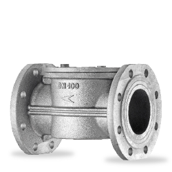
Safety shut-off valve/overpressure shut-off valve
is installed after the filter and before the pressure regulator.
The overpressure shut-off valve closes the gas supply if the downstream pressure exceeds a specified limit value.
07.
Gas regulator
is a control valve that reduces the inlet pressure of a fluid at its outlet to a desired value.
08.
Pressure gauge
The pressure gauges are installed to monitor the upstream and downstream pressure.
A shut-off valve is connected upstream of each pressure gauge to allow easy replacement of the pressure gauges in the event of a fault.
09.
Safety blow-off valve
is set to a higher pressure than the overpressure shut-off valve so that the safety blow-off valve operates when the overpressure shut-off valve is not working.
10.
Pressure switches
are intended for switching a circuit on and off or switching it over when the actual pressure value changes depending on the pressure setpoint.
11.
Solenoid valve
are intended for securing and controlling the air and gas supply to gas burners and gas appliances.

01.
Shut-off ball valve
To separate the gas control line from the supply.
02.
Solenoid shut-off valve
For gas separation, e.g. triggered by a gas detector.
03.
Manually operated quick-closing valve
For fast and safe closing with minimized pressure loss when open. Remote monitoring is possible. The closing process is faster and safer than with conventional ball valves.
04.
Pressure gauge
The pressure gauges are installed to monitor the upstream and downstream pressure. A shut-off valve is connected upstream of each pressure gauge to allow easy replacement of the pressure gauges in the event of a fault.
05.
Gas filter
protects the rest of the system from dirt or dust that is carried along with the gas flow. Deposits can, for example, consist of parts that were accidentally left in the pipe during construction.
06.
Safety shut-off valve/overpressure shut-off valve
is installed after the filter and before the pressure regulator. The overpressure shut-off valve closes the gas supply if the downstream pressure exceeds a preset limit value.
07.
Gas regulator
is a control valve that reduces the inlet pressure of a fluid at its outlet to a desired value.
08.
Pressure gauge
is set to a higher pressure than the overpressure shut-off valve so that the safety relief valve operates if the overpressure shut-off valve does not work.
09.
Safety blow-off valve
is set to a higher pressure than the overpressure shut-off valve so that the safety relief valve operates if the overpressure shut-off valve does not work.
10.
Pressure switch
To separate the gas control line from the supply.
11.
Solenoid valve
are intended for securing and controlling the air and gas supply to gas burners and gas appliances.
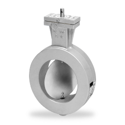
Gas volume control dampers
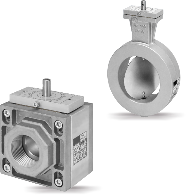
The gas volume control dampers are used to control the volume flow of gas or air.
The valves are manufactured in accordance with DIN EN 161 and DVGW-tested.
The valves are purely control valves without zero shut-off (residual leakage approx. 1 % of the max. KV value) and must not be used as shut-off devices
– Manually operated with hold-open device
– With electric actuator
– With pneumatic actuator
– With solenoid actuator
Housing
Aluminum
Shaft
AISI 303
Disk
Aluminum or AISI 304
Max. Pressure
500 mbar
Temperature
Gas: -10 °C to +60 °C Air -10 °C to +80 °C (up to 200 °C on request)
Control ratio
10:1
Plug valves
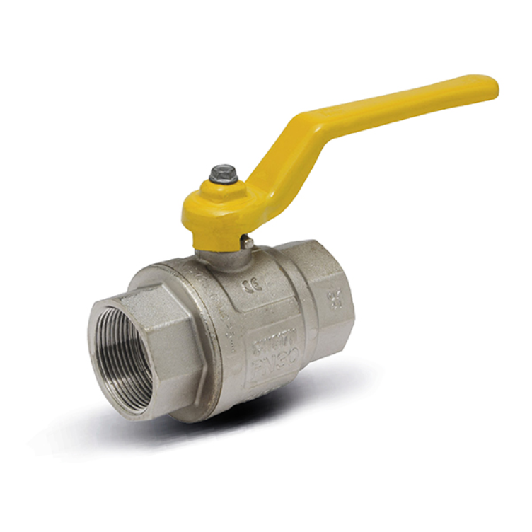
Ball valves are used to shut off gas or air.
Ball valves for gas applications can be used for gases of the first, second and third gas family.
Ball valves can be supplied with female inch threads, male inch threads or flanged versions.
The ball valves are CE-certified and manufactured in accordance with EN 331 (threaded version) and EN 13774 (flanged version).
- Manually operated (optionally with locking device)
- With electric actuator
- With pneumatic actuator
Housing
Aluminum
Shaft
AISI 303
Disk
Aluminum or AISI 304
Max. Pressure
500 mbar
Temperature
Gas: -10 °C to +60 °C Air -10 °C to +80 °C (up to 200 °C on request)
Control ratio
10:1
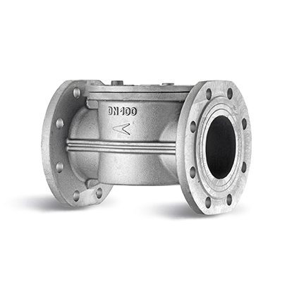
Gas filter
Gas filters designed in accordance with the provisions of the DIN 3386 standard can be used for all types of natural gas, liquid gas or non-corrosive gases.
These filters are often used to protect control units, pressure regulators, measuring devices and in systems that require a high degree of filtration.
All filter covers are sealed with test point connections at both the filter inlet and outlet.
Max. Pressure
AISI 321/304
Perm. Temperature
-20 °C to +600 °C
Degree of filtration
16 bar (air)
4 bar (gas)
Connection
as required
Housing
Aluminum
Gasket
NBR
Authorization
PED 2014/68/UE
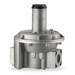
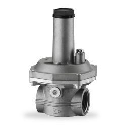
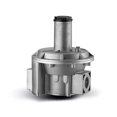
Gas pressure regulator
Spring-loaded regulators are designed and built according to DIN EN 88 Class A – Group 2 specifications.
They can be used for all types of natural gas, LPG or non-corrosive gases.
These regulators are often used in supply lines for mixing and combination burners and in the pipeline distribution of methane gas and LPG in industrial and non-industrial applications.
Not suitable for corrosive gases.
Spring-loaded regulators operate automatically with a balanced piston and double safety diaphragm.
The double diaphragm allows the device to be used in the switch cabinet without connecting an external pipe vent.
(Point 3.3.2 of the EN 88 standard).
All regulators have an internal measuring line and a test point for the inlet and outlet pressure.
Max. inlet pressure
0.5; 1; or 2 bar
Outlet pressure
10 to 300 mbar
Connection
½" to 2″ (threaded connection)
DN25 to DN150 (flanged connection)
Temperature range
-20 °C to +60 °C
Authorization
DIN EN 88-1:2011 PED
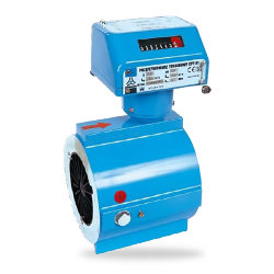
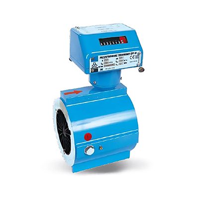
Gas meter
Quantometers were developed to provide a reliable and cost-effective measuring device (non-fiscal) with similar features to the turbine meter.
They are maintenance-free and can be connected to external devices.
The gas flow meter evaluates the ratio between the incoming gas and the wheel speed.
The rotational speed is proportional to the operating volume flowed through.
The rotary movement activates the measuring unit on the top of the quantometer via a mechanical/magnetic coupling, which reports the gas volume during operation.
The quantometers are CE and PED 2014/68/EU certified.
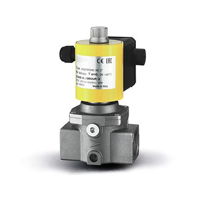
Solenoid valves
Automatic gas solenoid valves are used for the safety and control of gases for shutting off in gas supply lines.
Suitable for various gases including natural gas, propane and LPG gas.
Solenoid valve optionally NO or NC (normally open or normally closed).
Not suitable for aggressive gases.
- Fast closing < 1 s and slow opening 0.5 to 25 s adjustable
- Stage valve with 2 coils (stage 1 reduced flow, stage 2 full flow)
- Valve group
- Air valve (de-energized open)
- Solenoid valve with manual reset
Pmax
360 mbar/6 bar
Actuation time
Opening under 1 s;
Closing under 1 s
Tension
230 V AC; 115 V AC, 24 V DC
Temperature range
-20 °C to +60 °C
Connection
½" to 2″ DN 25 to DN 100
Protection class
IP 65
Authorization
DIN EN 161
Safety relief valves/ overflow valves
Safety relief valves (overflow valves) are suitable for use in civil and industrial combustion systems for absorbing and discharging the excess pressure of gases of the first, second and third gas family to the outside.
They are used in all common combustion systems for furnaces, boilers, dryers and civil burners.
Not suitable for aggressive gases.
Pmax
500 mbar/690 mbar/1 bar
Switching pressure
0.4 to 500 mbar
Pressure housing
Brass/aluminum
Gasket
NBR
Temperature range
-15 °C to +60 °C
Switching capacity
6 A/250 V AC
Protection classApproval
IP 54/IP 44 as differential pressure switch
Connection
¼"

Valve testing system
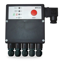
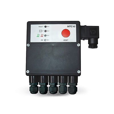
MTC10 is a device for checking the tightness of the two automatic valves before each start-up of the burner or after each shutdown.
Whenever a leak is detected at one of the gas valves, MTC10 prevents the burner from starting.
MTC10 is manufactured in accordance with the EN746-2 standard, which states that the installation of a leakage test is mandatory in installations with a capacity of over 1200 kW.
This device can be used on industrial and domestic gas burners with or without a vent pipe.
CE certified according to EN1643.
Conformity to Directive 2009/142/CE (Gas Directive), Directive 2004/108/CE (EMC) and Directive 94/9/CE (ATEX Directive).
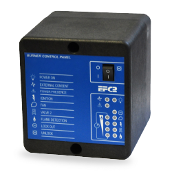
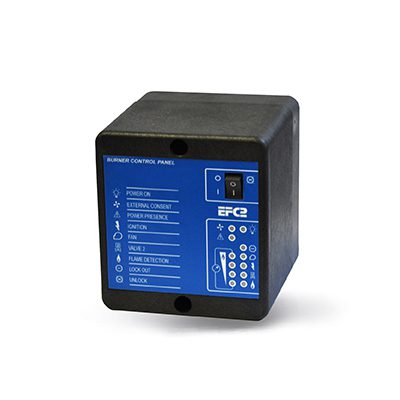
Burner control (EFC series)
The burner control units in the EFC series have been developed to detect a flame in single or two-stage industrial gas burners with intermittent operation.
The status of the burner is clearly indicated by the various LED lights on the front panel.
The EFC can be supplied with an internal ignition transformer and can also control one or two solenoid valves.
Flame detection can be via a single rod, two rods or a UV cell.
Remote control of the burner control is also possible.
The EFC series is supplied in a fireproof thermoplastic housing that allows installation next to the burner.
It is also available in a rack version for panel applications.
The EFC burner control unit is manufactured in accordance with EC Directive 90/396/EEC and EN298 standards.
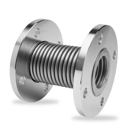
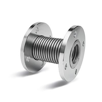
Stainless steel compensator
Flexible metal connections for gas to compensate for vibrations and misalignment of the pipeline.
Not suitable for absorbing torsional loads.
Available with threaded or flanged connection.
(Flanges loose on the expansion joint to avoid torsional loads).
Material
AISI 321
Max. temperature
300 °C
Max. Pressure
10 bar
Length
150 - 200 mm
Connection
½" to 2 ½" (threaded connection) DN50 to DN250 (flanged connection)
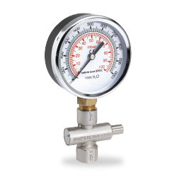
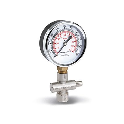
Pressure gauge
The pressure gauges are specially designed for measuring low pressures in mbar in accordance with EN 837-3 or high pressures in bar.
They are suitable for use in natural gas combustion systems and for measuring the pressure of non-corrosive liquids in a gaseous state.
They are available with a radial external thread 1/4″ – 3/8″ – 1/2″ and with a dial diameter of 63 – 80 and 100 mm.
The standard version is equipped with a double scale in mbar and in H2O mm.
A shut-off valve is connected upstream of each pressure gauge to allow easy replacement of the pressure gauges in the event of a fault.
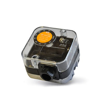
Pressure switch
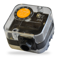
Pressure switches and differential pressure switches are suitable for use in combustion systems for detecting the pressure of gases of the first, second and third gas family and air.
They are normally used on the most common combustion systems such as ovens, boilers, dryers and compact burners.
The pressure switches are CE-certified according to the EN 1854 standards.
The operating pressure of the pressure switches can be adjusted via a handwheel.
Pmax
500 mbar/690 mbar/1 bar
Switching pressure
0.4 to 500 mbar
Pressure housing
Brass/aluminum
Gasket
NBR
Temperature range
-15 °C to +60 °C
Switching capacity
6 A/250 V AC
Protection classApproval
IP 54/IP 44 as differential pressure switch
Connection
¼"
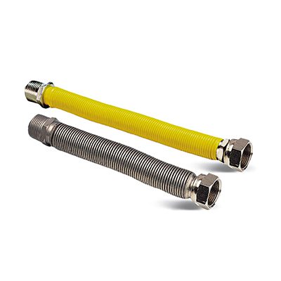
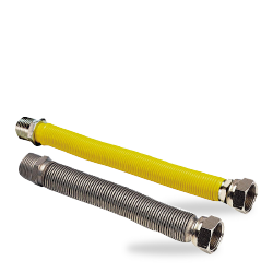
Flexible connection hoses
The flexible metal hoses are manufactured in accordance with DIN 3384 standards.
They are used in particular in industrial combustion systems to supply methane gas burners or other combustible gases of the first, second and third gas family and air.
Available with female threaded connection, male threaded connection or flanges.
Material
AISI 321/304
Temperature range
-20 °C to +600 °C
Max. Pressure
16 bar (air)
4 bar (gas)
Length
as required
Connection
3/8″ to 2″ (threaded connection)
DN10 to DN100 (flanged connection)
